A geared servomotor can be useful for rotary motion technology, but there are challenges and limitations users need to be aware of.
By: Dakota Miller and Bryan Knight
Learning Objectives
- Real-world rotary servo systems fall short of the ideal performance due to technical limitations.
- Several types of rotary servomotors can provide benefits for users, but each has a specific challenge or limitation.
- Direct drive rotary servomotors offer the best performance, but they’re more expensive than gearmotors.
For decades, geared servomotors have been one of the most common tools in the industrial automation toolbox. Geared sevromotors offer positioning, velocity matching, electronic camming, winding, tensioning, tightening applications and efficiently match the power of a servomotor to the load. This raises the question: is a geared servomotor the best option for rotary motion technology, or is there a better solution?
In a perfect world, a rotary servo system would have torque and speed ratings that match the application so the motor is neither over-sized nor under-sized. The combination of motor, transmission elements, and load should have infinite torsional stiffness and zero backlash. Unfortunately, real world rotary servo systems fall short of this ideal to varying degrees.
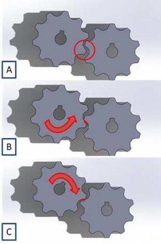
In a typical servo system, backlash is defined as the loss of motion between the motor and the load caused by the mechanical tolerances of the transmission elements; this includes any motion loss throughout gearboxes, belts, chains, and couplings. When a machine is initially powered on, the load will float somewhere in the middle of the mechanical tolerances (Figure 1A).
Before the load itself may be moved by the motor, the motor must rotate to take up all slack existing in the transmission elements (Figure 1B). When the motor begins to decelerate at the end of a move, the load position may actually overtake the motor position as momentum carries the load beyond the motor position.
The motor must again take up the slack in the opposite direction before applying torque to the load to decelerate it (Figure 1C). This loss of motion is called backlash, and is typically measured in arc-minutes, equal to 1/60th of a degree. Gearboxes designed for use with servos in industrial applications often have backlash specifications ranging from 3 to 9 arc-minutes.
Torsional stiffness is the resistance to twisting of the motor shaft, transmission elements, and the load in response to the application of torque. An infinitely stiff system would transmit torque to the load with no angular deflection about the axis of rotation; however, even a solid steel shaft will twist slightly under heavy load. The magnitude of deflection varies with the torque applied, the material of the transmission elements, and their shape; intuitively, long, thin parts will twist more than short, fat ones. This resistance to twisting is what makes coil springs work, as compressing the spring twists each turn of the wire slightly; fatter wire makes a stiffer spring. Anything less than infinite torsional stiffness causes the system to act as a spring, meaning potential energy will be stored in the system as the load resists rotation.
When combined together, finite torsional stiffness and backlash can significantly degrade the performance of a servo system. Backlash can introduce uncertainty, as the motor encoder indicates the position of the motor’s shaft, not where the backlash has allowed the load to settle. Backlash also introduces tuning issues as the load couples and uncouples from the motor briefly when the load and motor reverse relative direction. In addition to backlash, finite torsional stiffness stores energy by converting some of the kinetic energy of the motor and load into potential energy, releasing it later. This delayed energy release causes load oscillation, induces resonance, reduces maximum usable tuning gains and negatively impacts the responsiveness and settling time of the servo system. In all cases, reducing backlash and increasing the stiffness of a system will increase servo performance and simplify tuning.
Rotary axis servomotor configurations
The most common rotary axis configuration is a rotary servomotor with a built-in encoder for position feedback and a gearbox to match the available torque and speed of the motor to the required torque and speed of the load. The gearbox is a constant power device that is the mechanical analog of a transformer for load matching.
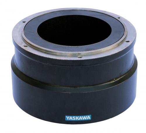
An improved hardware configuration uses a direct drive rotary servomotor, which eliminates the transmission elements by directly coupling the load to the motor. Whereas the gearmotor configuration uses a coupling to a relatively small diameter shaft, the direct drive system bolts the load directly to a much larger rotor flange. This configuration eliminates backlash and greatly increases torsional stiffness. The higher pole count and high torque windings of direct drive motors match the torque and speed characteristics of a gearmotor with a ratio of 10:1 or higher.
Post time: Nov-12-2021


